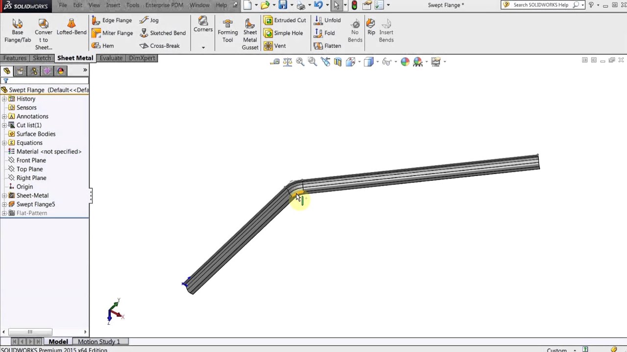
Describe The Creation Of A Sheet Metal Flange

Sheet Metal Flange Features

My Opinions On Sheetmetal Autodesk Community Community Archive Read Only

Sheet Metal Flange Manilupation Onshape
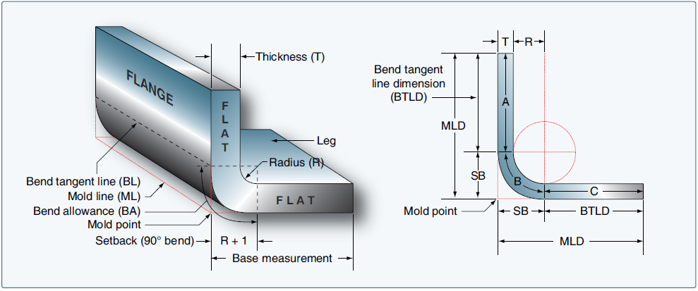
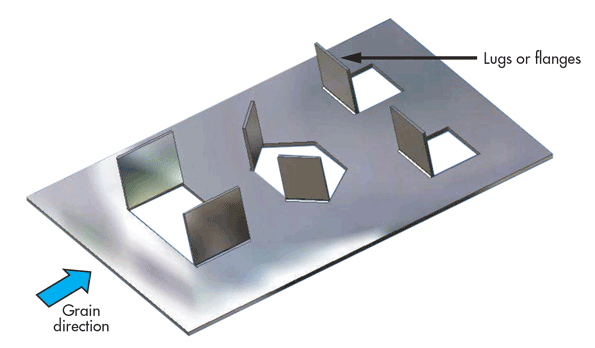
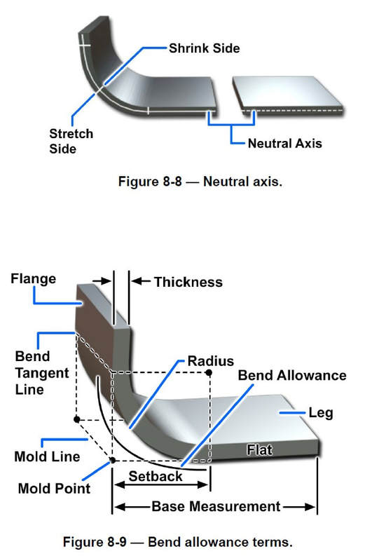
Aircraft Sheet Metal Layout And Forming Aircraft Systems

Flanges Clampco Products

Sheet Metal Design Guide Geomiq
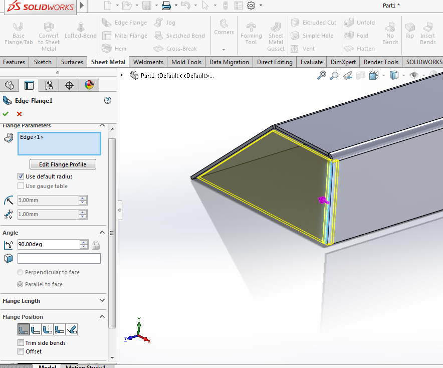
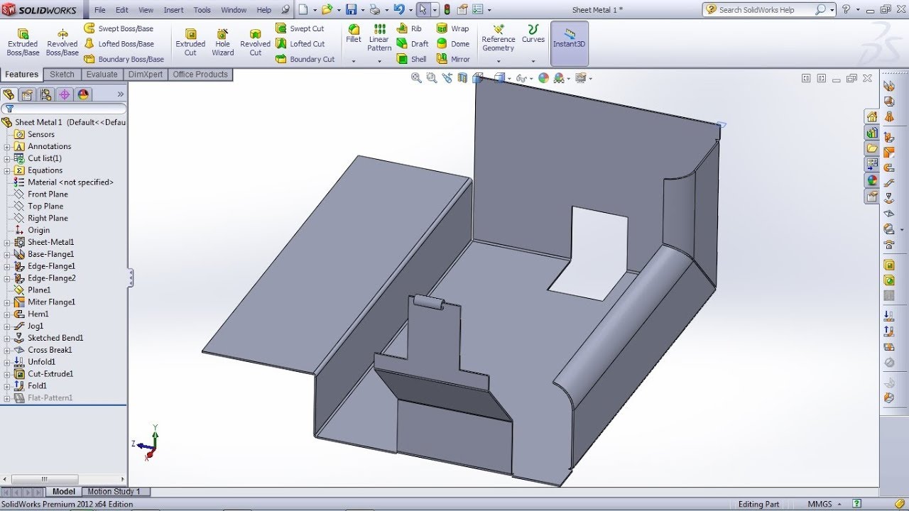
You can also specify the width or offset of the new flange.
Describe the creation of a sheet metal flange.
Sheet Metal Success In Solidworks Engineers Rule
Sheet Metal Design Guidelines How To Design Good Sheet Metal Parts

Sheet Metal An Overview Sciencedirect Topics
Sheetmetal Not Able To Make A Box Correctly Please Help Autodesk Community Fusion 360
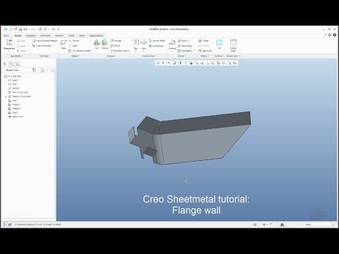
Creo Sheetmetal Tutorial How To Create Flange Wall Feature Youtube
Solidworks Sheet Metal Tutorial For Beginner 1 Base Flange Tab Edge Flange Miter Flange Hem Youtube
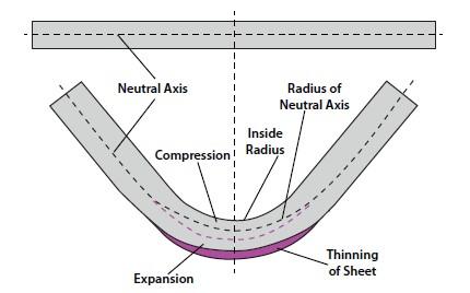
Analyzing The K Factor In Sheet Metal Bending

Solidworks Sheet Metal Gauge Table And Properties Youtube
Sweet Relief How To Avoid Hole Distortion In Sheet Metal Parts
Following Dfm Guidelines For Working With Sheet Metal Machine Design

Nx 11 Advanced Sheet Metal For Automotive And Aerospace Parts Nx Design
Developments And Intersection Drawings Computer Aided Drafting Design

Solidworks Tutorial Using The Jog Feature Lynda Com Youtube

Pin On Art

Solidworks Sheet Metal Tutorial Hopper Youtube Sheet Metal Drawing Sheet Metal Metal Sheet Design

Solidworks Tutorial Sheet Metal Edge Flange Youtube

Sheet Metal Understanding K Factor

Pin On Solidworks
Https Encrypted Tbn0 Gstatic Com Images Q Tbn 3aand9gcq Ezzigvpy99e1izogewhsfm Cw9r37y885aum1imvjg0nsrxh Usqp Cau

Solidworks Sheet Metal Lofted Bend Youtube
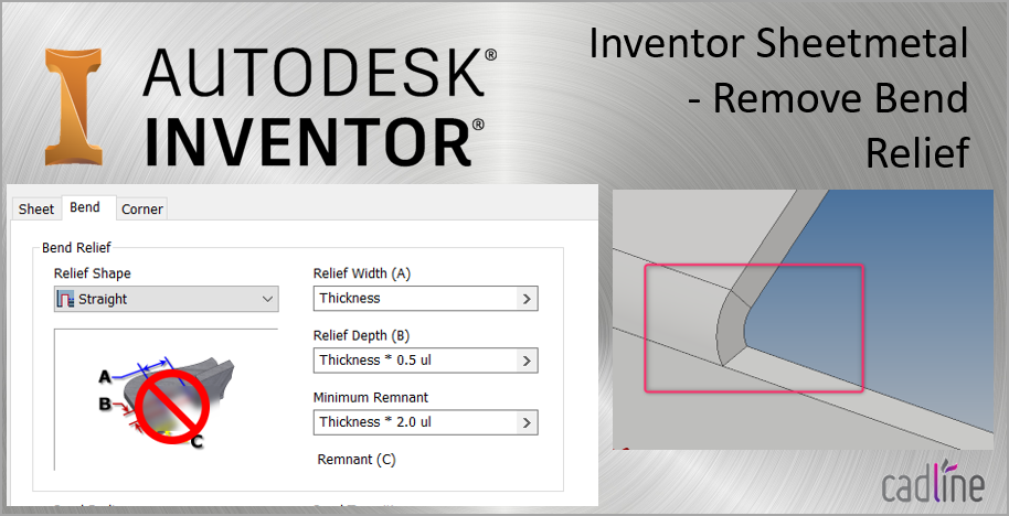
Inventor Sheetmetal Remove Flange Bend Relief Cadline Community
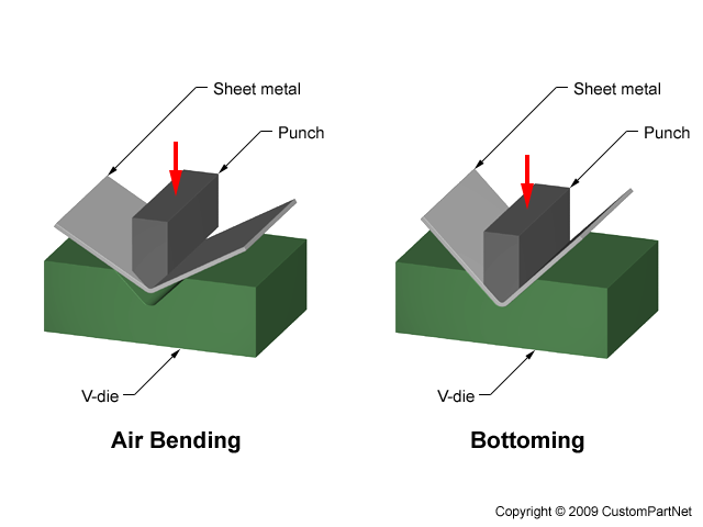
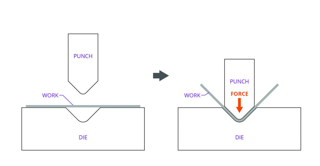
Sheet Metal Forming
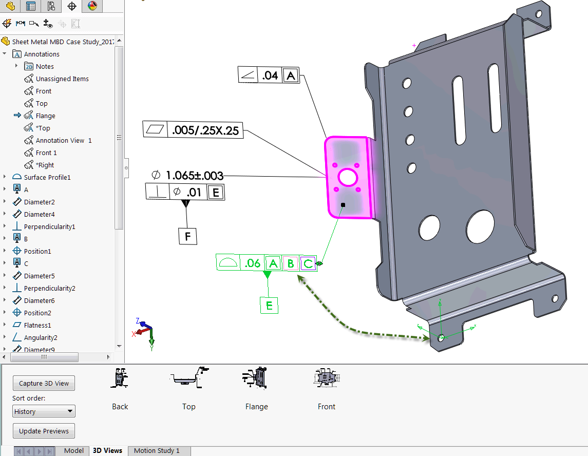
How To Define The Mbd Data Of Sheet Metal Parts Engineers Rule
Solidworks Swept Flanges And Miter Flanges Youtube
Source : pinterest.com
